1 4-point contact ball bearing
The four-point contact ball bearing (Figure 1) can withstand both axial loads and a certain degree of radial load, and provides very small axial positioning tolerances. At the same time, this type of bearing also saves installation space because it can be regarded as a combined version of two single-row angular contact ball bearings. Therefore, it is often selected for applications such as motors, gearboxes, compressors, and other scenarios.
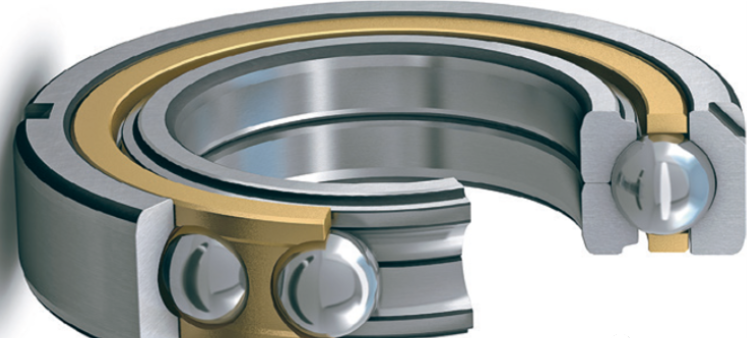
Figure 1 Four-point angular contact ball bearing
2 Details of the four-point contact ball shaft design
The standard four-point contact ball bearing (also known as the QJ series bearing) consists of an integral outer ring, a radial split inner ring, a ball group, and an outer ring guiding cage (see Figure 1).
The details of the bearing ring design are shown in the right figure. The outer ring is similar to the design of a deep groove ball bearing, but the cross-sectional shape of the raceway is slightly different. The raceway of a deep groove ball bearing is circular, while the outer ring of the four-point contact ball bearing consists of two symmetrical raceways. Each raceway is circular and intersects at one point in the middle of the bearing ring, and the centers of the two raceway arcs have a very small offset in the axial direction (Figure 2). The inner ring is divided into two halves, following the same design principle as the outer ring.
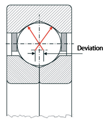
Figure 2 Section of a four-point contact ball bearing
A bearing with a 35-degree contact angle requires a higher raceway shoulder. Bearings with only a single integral inner ring can accommodate a smaller number of rolling elements. Therefore, four-point contact ball bearings adopt an open-type inner ring design, which enables them to accommodate the maximum number of rolling elements, with the number being limited only by the width of the cage crossbar.
3 Four-point contact ball bearing force application method
Theoretically, a ball has four distinct contact points with the bearing raceway (Figure 3a). This only occurs when a pure radial load is applied, but such a load condition is not necessarily present in real applications.
The most significant case is the application of pure axial load (Figure 3b), in which only two contact points at opposite diagonal positions transfer the load. If the axial load changes direction, these two contact points will move to the opposite positions. This explains why this type of bearing can withstand axial loads in both directions.
There are also some applications that have both radial and axial loads but with the axial load being the dominant one (Figure 3c). If a single row angular contact ball bearing is to achieve the same function, two identical bearings need to be configured back-to-back or face-to-face. This means that a four-point contact ball bearing can achieve a space-saving layout design.
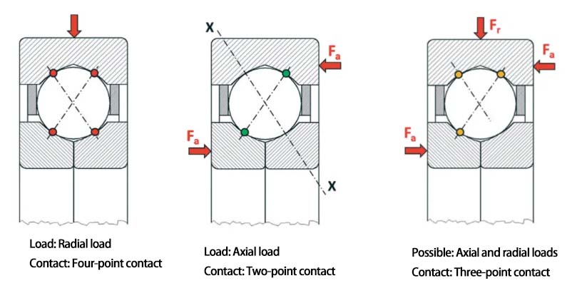
Figure 3 The force application mode of a four-point contact ball bearing
Two single-row angular contact ball bearings can be replaced by a four-point contact ball bearing, but there is an important condition: the four-point contact ball bearing can function correctly only when the axial load is the dominant force. The ratio recommended by SKF is Fa/Fr ≥ 1.27. While the load ratio requirement for angular contact ball bearings is Fa/Fr ≥ 1.
4 Design of bearing housing and end cover for typical applications of four-point contact ball bearings
In many applications, four-point contact ball bearings are used in conjunction with radial bearings such as cylindrical roller bearings. The key point here is that four-point contact ball bearings only bear axial loads. Therefore, the outer ring of the four-point contact ball bearing should not be axially clamped or radially clamped, but should be installed in the bearing housing with a radial clearance (a gap of 1 to 2 millimeters) (Figure 4). Otherwise, the outer ring may be subjected to additional frictional forces, resulting in unexpected additional forces within the bearing.
To prevent the outer ring from rotating, most bearings are equipped with an outer ring with two positioning slots (such as SKF four-point angular contact ball bearing QJ 212 N2MA, where N2 indicates the presence of two positioning slots). This allows the outer ring to be fixed to the bearing housing using a positioning pin (Figure 5).
It should be noted that the two halves of the inner ring must always be clamped axially.
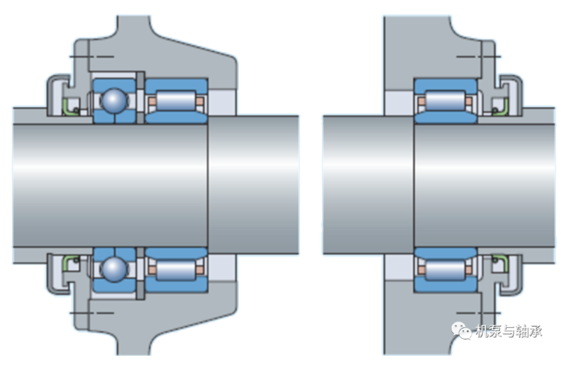
Figure 4 Typical application of four-point contact ball bearing
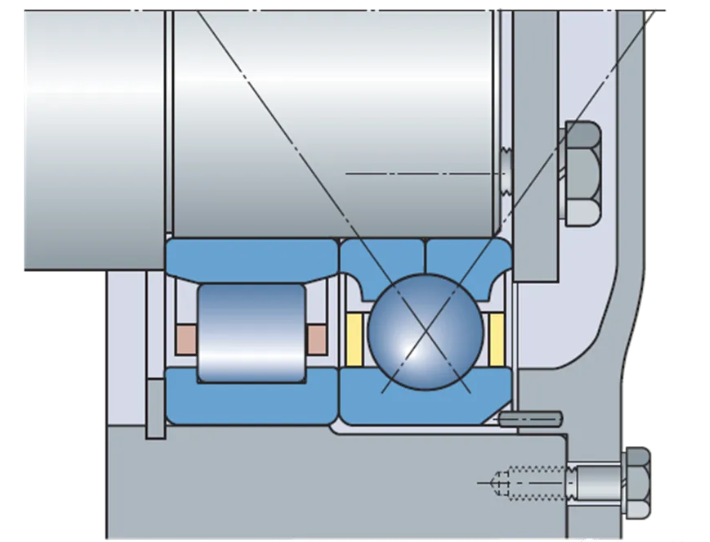
Figure 5 Outer ring positioning of a four-point contact ball bearing


WeChat official account

Scan and focus on us
Address:24th floor, Tianjin Property Building, 590 Shengan Road, Huishan District, Wuxi City, Jiangsu Province Tel : 13861477666 E-mail : jsdmdbearing@163.com ©2020 江苏帝蒙德轴承有限公司. 版权所有 苏ICP备16008043号-4