There is a very fatal cognitive error in the bearing industry: as long as the flaw detection is qualified and there are no visible cracks, the workpiece is considered a 100% qualified product. However, countless on-site cases have proved that the micro-level grinding micro-cracks that the instrument cannot detect are the biggest culprit for the early failure of bearings. Many bearings are fully qualified when they leave the factory, but after only a few hundred hours of operation, they start to peel, flake off, make abnormal sounds, and crack. The root cause is all the hidden micro-cracks on the surface. Today, by combining with the measured service life data, we will thoroughly explain the hidden dangers of micro-cracks, the detection blind spots, and the on-site prevention and control plans, helping everyone solve the problem of short lifespan of bearings from the root cause.
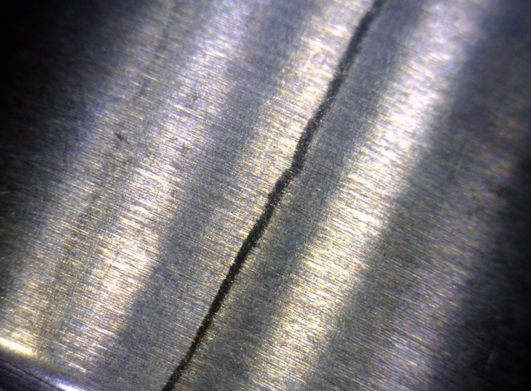
Figure: Close-up micrograph of wire drawing microcracks on the metal surface
Grinding micro-cracks are 1-20 μm closed and hidden cracks that occur on the surface of the workpiece under the combined action of thermal stress, compressive stress, and phase transformation stress. These cracks are extremely narrow, completely closed, and buried very shallowly. They cannot be identified by the naked eye, magnifying glass, or conventional roughness gauges. Conventional magnetic particle testing can only detect open cracks and defects with a depth of 50 μm or more; ultrasonic testing has very weak signal reflection for closed micro-cracks, and there is a frequency band mismatch; eddy current testing is only sensitive to surface open defects. Grinding micro-cracks belong to a typical "closed, shallow, and sub-microscopic" triple blind zone superimposed defect. Conventional quality inspection methods simply cannot reach it, which is the core reason why it can deceive and pass.
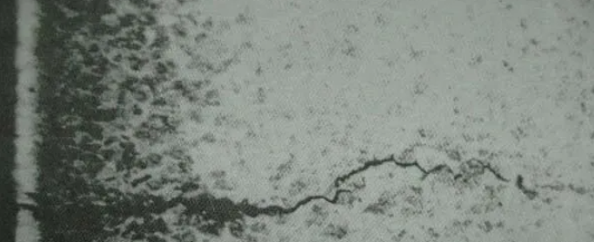
Figure: Observation of cracks under a metallographic microscope
The formation of micro-cracks during grinding is essentially the result of the triple stress coupling of "heat, force and phase change" that causes the surface layer to tear. The grinding wheel undergoes high-speed friction, generating heat, and the surface temperature can soar to 800-1200℃ (far exceeding the material's phase transition point). The surface structure expands due to heating; the grinding fluid or air rapidly cools the surface, causing it to contract instantaneously. The combined effect of thermal expansion and contraction generates a huge tensile stress. At the same time, the squeezing effect of the grinding wheel brings mechanical compressive stress, and the phase change of the grinding wear layer brings organizational stress. These three stresses are superimposed within the thin layer, and when they exceed the material's tensile strength limit at that instant, micro-cracks of micrometer scale form on the surface. After cooling, the tissues on both sides of the crack rebound and adhere, forming a "closed state" micro-crack - this is the fundamental reason why it is difficult to detect.
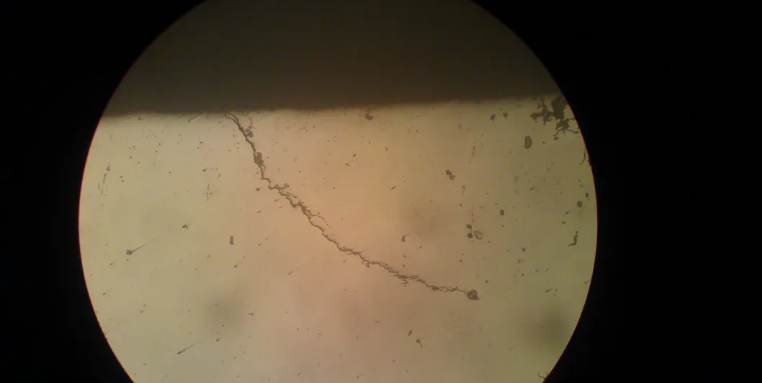
Figure: Microscopic image of microcracks morphology
We conducted a fatigue life test on the same batch of bearings (GCr15 bearing steel, P2 grade accuracy). The results were truly astonishing: high-quality bearings without any microscopic cracks can have an average lifespan of over 8,500 hours under rated conditions (rotational speed of 12,000 rpm, radial load of 1.2 kN); bearings with shallow surface grinding micro-cracks (depth ranging from 5 to 15 μm) have an average lifespan of only 2,200 to 2,800 hours, with a direct reduction of over 70% in lifespan. The maximum difference can even reach 80%, meaning that a high-quality bearing lasts for 8,500 hours while a poor-quality one fails prematurely after only 1,600 hours. These data are the average values from the batch production site statistics and are not extreme laboratory samples. They are sufficient to demonstrate the devastating impact of micro-cracks on lifespan.
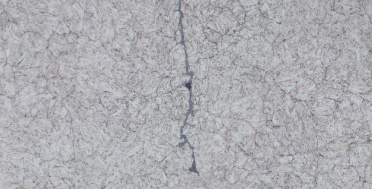
Figure: Comparison of gold micro-cracks at a 20 μm scale
The most troublesome aspect of microcracks lies in their "growth nature" - once they emerge, they cannot stop. During the operation of the bearing, it continuously withstands alternating loads, speed fluctuations, temperature cycles, and frictional impacts. Each cycle exerts a tearing-type tensile stress on the crack tip. The stress concentration coefficient at the crack tip is extremely high (up to 3-5 times the material's yield strength), and the crack tip advances by a few nanometers to a few micrometers each time. After tens of thousands or hundreds of thousands of cycles, shallow microcracks will propagate along grain boundaries or through the crystal lattice, gradually connecting, branching, and eventually forming macroscopic cracks, leading to surface peeling, bearing seizure, and structural fracture. The propagation of microcracks is irreversible; once they emerge, they are destined to burst.
The first cause is excessive thermal stress: the abrasive wheel becomes dull, the cooling is uneven, and the feed rate is high. After the surface layer reaches a high temperature, it rapidly contracts, resulting in tensile microcracks, which is the main cause. The second cause is the brittleness of the surface material: the grinding deteriorated layer and the white layer area have a significant increase in brittleness. The toughness index may drop from 80J/cm² of the base material to below 20J/cm², easily generating network microcracks. The third cause is the superposition of process stress: excessive leftover material during rough grinding (more than 0.1mm on one side), insufficient fine grinding, and concentrated residual stress, which trigger surface cracks. These three causes exist almost simultaneously in the rough grinding site. Therefore, the high incidence of microcracks is not an accidental event but a necessary result of inadequate process.
Conventional flaw detection equipment (magnetic particle, ultrasonic, eddy current) is only effective for open cracks and deep cracks (> 50 μm). For closed, shallow, and sub-microscopic grinding micro-cracks, the equipment cannot capture the signals and they are directly judged as qualified. This "qualified detection" is highly deceptive - it only proves the absence of obvious large cracks, but cannot prove the absence of microscopic cracks. This is the core vulnerability for the early failure of batch bearings. High-end bearing manufacturers (such as SKF and NSK) conduct metallographic inspections, acid washing and penetration testing, and multi-dimensional microscopic hardness testing on the surface of bearings to escape the blind spots of conventional flaw detection. A test report with only the conventional flaw detection seal is far from sufficient for the long-life requirements of bearings.
For the mass production of precision bearings, periodic gold phase inspection and acid washing and penetrant testing must be carried out to accurately detect micro-cracks at the micron level, compensating for the shortcomings of conventional flaw detection. Specific plan: The inspection ratio for each batch should not be less than 5%, and 100% gold phase inspection for key components; the gold phase sample preparation adopts the oblique cutting method (5° - 10° oblique cutting), with an observation magnification of 200 - 500 times; the acid washing uses 5% nitric acid alcohol, and the corrosion lasts for 15 - 30 seconds before observing the distribution of network cracks. Once micro-cracks are detected by gold phase inspection, the entire batch should be reworked or downgraded. The gold phase inspection should be solidified into the SOP to upgrade from "qualified assembly" to "pure surface qualified", and to prevent hidden defects from occurring before the product leaves the factory.
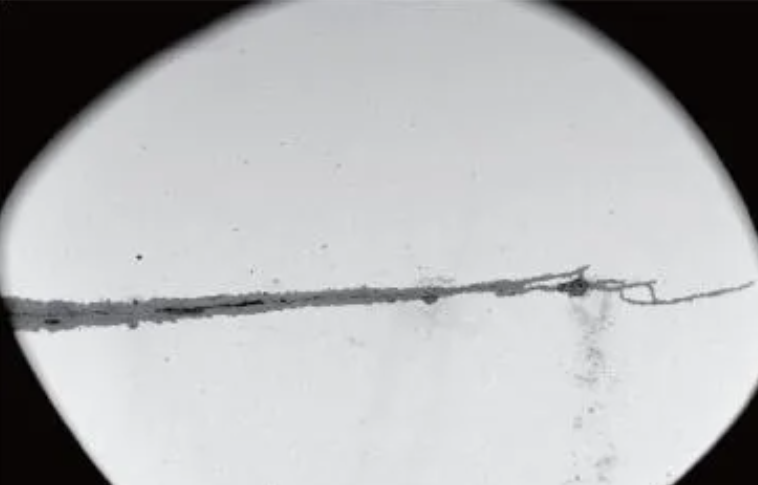
Figure: Microscopic view of material micro-cracks at a 2 μm scale
Thermal stress is the primary cause of micro-cracks, and controlling the temperature is controlling micro-cracks. Continuously monitor and control the grinding temperature to prevent high-temperature burns: during the rough grinding stage, the linear speed should not exceed 30m/s, and the feed rate should not exceed 0.02mm/rev; during the fine grinding stage, the linear speed should be reduced to 20-25m/s, and the feed rate should not exceed 0.005mm/rev. Optimize the cooling spray coverage to ensure that the spray nozzle angle is aligned within 5mm of the grinding contact point, with a spray flow rate of no less than 20L/min, and the grinding fluid temperature should be stable at 20-30℃. Regularly adjust the grinding wheel (perform adjustments every 50-100 pieces). Maintain sharp cutting to reduce mechanical compression stress. By combining parameters, cooling, and grinding wheels, the thermal stress is compressed at its source, and the probability of micro-cracks occurring can be reduced by more than 80%.
The process allowance ratio is the final barrier for preventing microcracks. Reasonably distributing the allowances for rough and fine grinding, do not rush during rough grinding, and control the unilateral removal amount within 0.05-0.1mm; for fine grinding, fully remove the stress layer and microcrack layer generated during rough grinding, and the unilateral fine grinding allowance should not be less than 0.01-0.02mm, ensuring that the surface damage tissue on the product is completely removed. The finishing process (grinding/ultra-finishing) serves as the final step, and another 0.005-0.01mm is further removed to maximize the guarantee of the product surface being pure and free of hidden defects. The allowance ratio of the three processes of rough grinding, fine grinding, and finishing is the core process parameter for microcrack prevention. If the ratio is reasonable, microcracks can be controlled below the visible limit of 2μm in the metallographic view; if the ratio is imbalanced, even the best equipment and cooling cannot make up for it.


WeChat official account

Scan and focus on us
Address:24th floor, Tianjin Property Building, 590 Shengan Road, Huishan District, Wuxi City, Jiangsu Province Tel : 13861477666 E-mail : jsdmdbearing@163.com ©2020 江苏帝蒙德轴承有限公司. 版权所有 苏ICP备16008043号-4