Mechanical drawing is known as the "engineer's language", which uses lines, symbols and numbers to condense complex mechanical structures and manufacturing requirements into square drawings. However, for beginners, it is often difficult to get started in the face of dense views, dimensioning and technical requirements. How to "read" the form and function of three-dimensional entities from two-dimensional drawings? How to understand the designer's intention and translate it into actual processing? This article will systematically analyze the reading logic of mechanical drawing to help you cross the gap between two-dimensional and three-dimensional thinking.
Map Reading Basics: Understanding the "grammar rules" of drawing
The core of mechanical drawing lies in standardization and projection logic. Before reading the drawing, you must master the following basics:
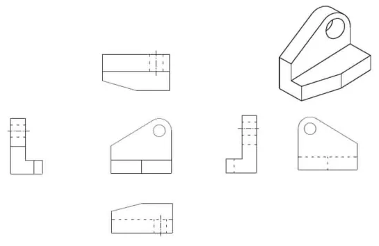
Projection principle: The three views (main view, top view, left view) of the "long on the right, height, width equal" law is the basis of reading.
As a simple example, the three views view an object from three angles. We can get information about the object on the corresponding surface.
For example, the main view reflects the length and height of the object, the top view shows the length and width, and the left view shows the height and width.
Symbolic language:
Line type: thick solid line (visible outline), thin dotted line (invisible outline), dotted line (symmetrical center line), etc., different lines represent different spatial positions.
Marking rules: the direction of the size number, the tolerance symbol (such as Φ represents the diameter), the surface roughness symbol (such as √ represents the machining surface), etc., must strictly follow the national standard (such as GB/T).
View type:
Section view: Show the internal structure through the imaginary cutting plane, pay attention to the position and direction of the cutting symbol.
Local magnification: magnify and mark small structures to avoid misreading caused by size density.

Reading method: from "Disassembly" to "Reconstruction"
Spatial imagination is the core of picture reading, and common methods include:
Body analysis:
The complex parts are decomposed into basic geometry (such as cuboid, cylinder, cone, etc.), and the relationship between shape and position is analyzed one by one.
Key steps:
(1) Determine the overall outline from the main view;
(2) Look for feature wireframes in the top view and left view (such as circle corresponding to cylinder, rectangle corresponding to prism);
(3) Judge the up and down, left and right, front and back positions of each part by "projection".
Line and surface analysis:
Suitable for cutting body or curved complex parts, infer the surface shape by analyzing the closed wireframes, intersecting lines (such as intersecting lines, intersecting lines) in the view.
Skill:
If a wireframe corresponds to a slant in another view, the plane may be a slant.
If polygons appear in multiple views, they may be projections of polyprisms.
Stretching method:
"Stretch" feature wireframes in a 2D view to a 3D entity along the projection direction. For example, a rectangular wire frame in the main view is stretched vertically to form a cuboid, and a circular wire frame is stretched to form a cylinder.
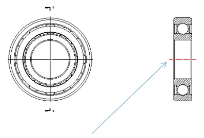
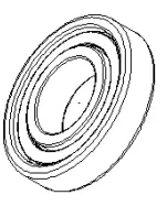
Taking bearing drawings as an example, bearings are used as rotary body graphics, and most shapes can be generated by rotation.
The selection of this center line as the axis can generate the inner and outer rings of the bearing

Advanced reading: "Code interpretation" of dimensions and tolerances
The size and tolerance on the drawing are the "legal basis" of manufacturing, and the reading of the drawing needs to focus on:
Size reference:
Design basis: the functional basis of the part in the machine (such as the center line of the shaft);
Process reference: the positioning reference (such as the end face or bottom surface) during processing.
For example, the diameter of the tooth tip circle of the gear is based on the axis of the center hole, and the depth of the keyway is based on the outer circle of the shaft.
Tolerance and fit:
Dimensional tolerance: such as Φ30±0.01, it means that the size is allowed to fluctuate between 29.99~30.01mm;
Geometric tolerance: such as parallelism, roundness symbol, to ensure the accuracy of the movement of parts after assembly;
Coordination code: such as H7/g6, indicating that the hole and the shaft are clearance coordination, suitable for rotating moving parts.
Technical requirements:
Material hardness (such as HRC 50-55), heat treatment process (such as quenching + tempering), surface treatment (such as chrome plating) and other text descriptions directly affect the selection of processing technology.
Error-prone point warning:
Ignore the default requirement for "unnoted tolerance" (usually marked near the title bar);
Misreading the sign direction of surface roughness leads to confusion between machined surface and non-machined surface.
Modern technology enables: from traditional drawing to digital reading
With the popularization of CAD (Computer Aided Design) and 3D modeling technology, the way of reading drawings is changing:
Reverse modeling: By importing 2D drawings to SolidWorks, UG and other software, quickly generate 3D models to verify the rationality of the design;
Ai-assisted image reading: Machine learning algorithm is used to automatically identify view relationships and label potential conflict dimensions;
AR visualization: 2D drawings are superimposed on real scenes through augmented reality devices to assist in assembly and maintenance.
However, no matter how the technology advances, the solid basic skills of graph reading are still the core competitiveness of engineers. Only by understanding the design intent can we navigate the era of intelligent manufacturing.
Conclusion: Drawing is the bridge of thinking
Understanding mechanical drawing is not only the embodiment of technical ability, but also the training of engineering thinking. It requires us to switch freely between two and three dimensions, to balance the details and the whole, and to seek breakthroughs between standards and innovation. Just as Da Vinci's manuscript combines art and science, mechanical drawings are also the crystallization of human wisdom and industrial civilization. To master this "language" is to open the door to the mechanical world.