Abstract: This paper analyzes and studies the causes of the burn out of the bearing of the straightener roller in the second mill, and makes improvements according to the causes, which greatly reduces the incidence of the burn out accident of the straightener and improves the production efficiency of the second mill.
Key words: Straightener; Straightening roll; bearing
antecedent
After the car straightening machine was put into use in Shaosteel No. 2 Rolling plant, the straightening roller burning event occurred frequently. From the beginning of June 2011 to the end of August, a total of four sets of roller base devices needed to be replaced in just two months, which seriously affected the normal production of the No. 2 rolling plant and brought great economic losses to the No. 2 rolling plant.
1 Cause Analysis
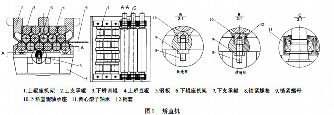
The straightener structure is shown in Figure 1. The straightening machine includes two parts: upper roller and lower roller. The upper roller mainly includes the upper roller seat frame 1, the upper straightening roller 4 and the upper supporting roller 2, and the lower roller mainly includes the lower roller seat frame 6, the lower straightening roller 3 and the lower supporting roller 7. The straightening roll and support roll are connected to the bearing seat by aligning roller bearings. Upper back-up roll 2 and upper straightening roll 4 are in contact with each other. The function of upper back-up roll 2 is to bear the radial force transmitted by upper straightening roll 4 and increase the rigidity of upper straightening roll 4. Similarly, lower back-up roll 7 and lower straightening roll 3 are in contact with each other. The function of lower back-up roll 7 is also to bear the radial force transmitted by lower straightening roll 3 when it is working, which increases the rigidity of lower straightening roll 3. When working, the motor drives the lower straightening roller 3 to rotate, and the lower straightening roller 3 drives steel plate 5 through the upper straightening roller 4 and the lower straightening roller 3. By adjusting the distance between the upper roller frame 1 and the lower roller frame 2, the rolling force of the straightening machine on steel plate 5 can be adjusted, so as to achieve the purpose of straightening steel plate.

In the working process, the straightening roller will bear the radial and axial forces caused by the deformation of steel plate 5. The radial force is transferred from the straightening roll to the supporting roll, and is finally borne by the supporting roll, while the axial force is mainly borne by the bearing and bearing seat connected with the straightening roll. Because the axial force bearing capacity of self-aligning roller bearing is low, too much axial force is the main cause of bearing damage.
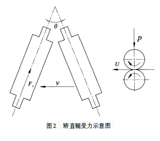
The stress diagram of the straightening roll is shown in Figure 2. During the operation of the straightener, the main reasons for excessive axial force are as follows:

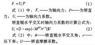
There are three kinds: one is that the straightening roller lines are not parallel and cross horizontally, the other is that the straightening roller lines cross vertically, and the third is the periodic axial force brought by the transmission device. Among them, the first two are the main causes of excessive axial force. There is a dependent relationship between the axial force generated by the crossing of the straightening roller and the straightening force. The formula is as follows:

According to equations (1) and (2), U1=0 when the straightening roller has no horizontal crossover (θ=0); The axial force F1 is 0; With the increase of the crossing Angle θ of the straightening roller, the axial force coefficient U1 increases, and the axial force F1 also increases [1]. In 1978, when analyzing excessive burning of rolling mill bearings caused by axial force in the United States, it was proposed that the axial force F1 depends on the straightening force P and the intersection Angle θ. When all parts of the mill are well manufactured and assembled, the axial force F1 is about 0.5% ~ 10% of the straightening force P. If the straightening rollers cross, the axial force F of the straightening rollers is about 5% of the straightening force P [2].
Therefore, reducing the cross of the straightening roller lines and ensuring the parallelism of the straightening roller lines is the most effective way to reduce the axial force of the straightening roller and avoid the damage of the straightening roller.
The factors causing the unevenness of the straightening roller line are as follows.
(1) Reasons for equipment manufacturing and installation. As shown in Figure 1, both ends of straightening roll 3 are connected to bearing seat 10 through aligning roller bearing 11, and bearing seat 10 is fixed on lower roller seat frame 6 through screw 8 and nut 9. The positioning of bearing seat 10 is realized by matching the positioning boss on the upper part of the bearing seat with the positioning hole on the lower roller seat frame 6. Therefore, the matching accuracy of bearing seat positioning boss and bearing seat positioning hole, the position accuracy of frame positioning hole, the dimensional accuracy of bearing seat and other factors will affect the parallelism of straightening roll line, that is, the parallelism of straightening roll line depends on the manufacturing accuracy of equipment. Therefore, only when the manufacturing accuracy of the equipment is very high, the parallelism of the straightening roller line can meet the requirements. Otherwise, when the manufacturing accuracy of the equipment is low, the accumulation of errors of various dimensions will lead to the straightening roller line is not parallel, so that the straightening roller bearing will bear a large axial force when working.
(2) Long-term use of equipment causes aging. In the process of working, the straightener often bears greater impact force, which is easy to cause loosening of fastening bolts. The loosening of the fastening bolt, on the one hand, the positioning boss of the bearing seat and the positioning hole on the frame are not tight, long time work will make the positioning boss and positioning hole wear each other, the wear will affect the positioning accuracy of the bearing seat, thus affecting the parallelism of the straightening roller shaft line. On the other hand, the loosening of the bolt will cause the bearing seat to deform under the impact force, thus affecting the parallelism of the straightening roller line.
In addition, when working, the thickness of both sides of the steel plate is poor, and the processing accuracy of the straightening roller can also cause the straightening roller lines to cross.
In actual production, when the straightener is used for a certain period of time, the bearing seat positioning hole on the frame is obviously worn, which has changed from round to oval. The measurement data shows that the roundness deviation of the positioning hole of the bearing seat is up to 2mm. Such serious wear makes the position of the bearing seat seriously offset, which leads to the intersection Angle of the straightening roller line θ increase, so that the bearing bears a large axial force F1 for a long time, and the bearing is therefore easy to be damaged. The axial force F1 caused by the increase of cross Angle 0 of straightening roller will even cause deformation of bearing seat gland and break of fastening bolt.
2 Improvement Measures
From the above analysis, it can be seen that in order to ensure the working stability of the straightener and reduce its maintenance frequency, measures should be taken to ensure the parallelism of the straightener shaft line and reduce the axial force borne by the straightener roll. Therefore, the following improvement measures are proposed.
(1) Reposition the bearing seat of the straightening roll. It is known from the above sub-plate that bearing damage is caused by the serious wear of bearing positioning holes on the frame, which causes the bearing seat to be offset and the straightening roller line to be not parallel. Therefore, this paper uses a new positioning ring to replace the original bearing positioning hole to locate the bearing seat. The method is as follows: firstly, the bearing positioning hole is redrilled to increase the aperture of the positioning hole, and then the positioning ring is placed on the bearing positioning hole, so that the bearing seat positioning boss through the positioning ring is set in the bearing seat positioning hole, because the diameter of the bearing seat positioning hole is larger than the diameter of the bearing seat positioning boss, so the position of the bearing seat can be adjusted appropriately according to the needs. Adjust the axis parallelism between the straightening rollers with the help of measuring instruments. When the parallelism of the straightening roller shaft line is adjusted well, weld the positioning ring on the straightening roller frame so that the bearing seat is completely positioned. In order to strengthen the stability of the straightening roller bearing seat and eliminate the axial force caused by the vibration of the bearing seat, the positioning ring and each bearing seat are prepared and processed, so that the matching gap between the positioning boss and the positioning ring of the bearing seat is less than 0.1mm.
(2) Before installing the straightening roll, test the roundness tolerance of the straightening roll, cylindricity tolerance and roundness tolerance of the inner hole of the bearing seat. Process and correct the straightening roll whose roundness tolerance is greater than 0.1mm and cylindricity tolerance is greater than 0.2mm and the bearing seat whose roundness tolerance is greater than 0.15mm, so as to reduce the impact force suffered by the straightening roll in the working process.
(3) In daily use, strengthen the daily maintenance and repair of the straightening machine, and regularly detect the wear of the straightening roll and the tightness of the bearing seat to ensure that the bearing seat is in a stable working state.
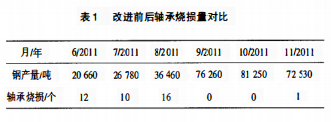
Straightener through the above improvement, the working condition is stable, bearing damage frequency can also be reduced. In the second half of 2011, the number of bearing burn and steel output of the straightener at Shaosteel No. 2 Rolling mill was statistically found (see Table 1). Before improvement (from June to August), the number of bearing burn per month was as few as 10, and the number of bearing burn per month was mostly 16. After the improvement (from September to November), only one bearing was burned in three months, and the straightening roller worked stably. Therefore, the steel output of the second mill increased steadily to more than 70,000 tons. It can be seen that the above improvement measures are based on the correct analysis of the working condition of the straightener, which plays a key role in stabilizing the working condition of the straightener and improving the production efficiency of the second mill.

3 Closing remarks
Rolling mill production environment is bad, can cause the straightener bearing damage factors are more, straightener bearing damage is not the result of a single factor, but a variety of factors led to the comprehensive action. No matter what the original factors that lead to the damage of the straightener bearing are, the main principle is that the external factors lead to the straightener roller line is not parallel, resulting in huge axial force, so that the bearing damage ring. Based on this principle, this paper takes effective measures to transform the straightener and strengthen the daily maintenance management, so that the straightener can maintain a stable working condition, thus improving the production efficiency of the second mill.
【 Reference 】
[1] LIU Renfu. Preliminary Study on Axial Shifting of Roll in Backroll Medium Plate Mill [J]. Steel Rolling, 1995(6):6-10.
[2] ZHAO Lin. Research Status and Development of Axial Force in Rolling [J]. Steel Rolling, 1997(1):47-49.