
Abstract: The stress distribution and deformation of the work roll bearing seat in rolling mill were analyzed at the interface end of the T connecting rod of the bending hydraulic cylinder and the thin wall thickness of the bearing seat under the bending force. The three-dimensional model of the analysis object is established by using the three-dimensional software, and the finite element model is established by using the general finite element software. The influence of the interface part of the T-shaped connecting rod and the wall thickness of the bearing seat on the deformation of the bearing seat is analyzed. It provides a theoretical basis for the design of work roll bearing seat of rolling mill.
Key words: finite element; Rolling mill; Bearing seat; Amorphosis
1 Introduction
With the rapid development of the cold-rolled strip processing industry, the precise control of the shape and size of the finished strip is becoming more and more demanding. In the process of strip production, each manufacturer uses the method of improving the rolling process and production equipment to control the shape of the plate.
Hydraulic roll bending technology of work roll is widely used to control the shape of rolling plate. The method of bending the roll can make the work roll bend accordingly to adjust and change the shape of the corresponding roll gap, and ensure that the flatness of the produced sheet meets the tolerance requirements.
Hydraulic roll bending plays a significant role in reducing strip crown, improving strip flatness, increasing productivity and reducing roll consumption, so it is widely used as one of the control methods commonly used in modern strip mills [1].
As an important working part of the rolling mill, the work roll bearing seat bears the action of roll bending force. In the rolling process, if the bending force is too large and the design wall thickness of the bearing block is not strong enough, the working roll bearing block and the T connecting rod of the bending hydraulic cylinder and the lower end of the working roll bearing block are very thin under the action of the bending force, resulting in a large deformation of the bearing block and the phenomenon of stress concentration. At present, the main method to simulate the deformation of work roll bearing seat is the general finite element method. This paper uses the finite element method to simulate the deformation of the bearing seat, analyzes the influence of different design values on the deformation of the work roll bearing seat, and provides a practical basis for the design of the work roll bearing seat of the rolling mill [1].
2 Finite Element Model
2.1 Solid model and grid division
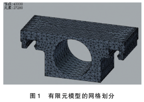
Firstly, the grid inside the static finite element model of the work roll bearing seat of the rolling mill is divided, as shown in Figure 1. And set the grid. The average element size is 0.05, the size of the smallest element is 0.1, the classification coefficient is 1.5, and the largest Angle is 60°.
2.2 Load and constraint
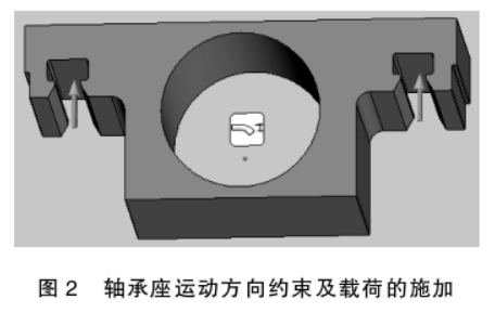
Before the static analysis of the bearing seat, according to its working condition, the inner ring is used as the constraint surface and the movement direction of its radial contact surface is fixed and restricted. The vertical load consistent with the bending force is applied to the two contact surfaces in the T-groove of the contact ends of the T-piston rod of the bending hydraulic cylinder, as shown in Figure 2.
3 Results and analysis
By analyzing the simulation results under different design conditions, the influence of different design variables on the deformation of the bearing seat can be obtained, including the wall thickness of the bearing seat and the bending roll force.
3.1 Simulation Conditions
(1) Work roll bending force: 550kN, calculated load of 550kN;
(2) Model establishment: Establish a three-dimensional model, define the work roller bearing material: 35 steel;
(3) Force analysis: The three-dimensional model is introduced, the inner ring of the bearing seat is fully constrained, and the two contact surfaces in the two T-slots at the upper end are loaded with external force under the pressure of 275kN each.
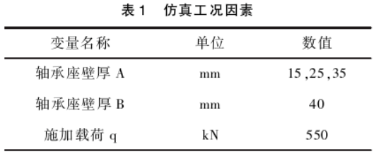
According to the conventional design value of the bearing seat in the design process, three representative wall thickness values A of the bearing seat are selected for simulation in this simulation, and the calculation conditions are shown in Table 1.
3.2 Bearing seat wall thickness A = 15mm
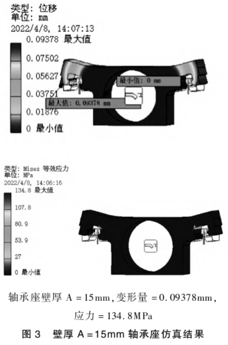
As shown in Figure 3, when the wall thickness of the bearing seat is A = 15mm, the maximum deformation of the T-groove is 0.09378mm, and the maximum stress of the bearing seat is 134.8MPa.
3.3 Bearing seat wall thickness A = 25mm
As shown in Figure 4, when the wall thickness of the bearing seat is A = 25mm, the maximum deformation of the T-groove is 0.09588mm, and the maximum stress of the bearing seat is 133.4MPa.
3.4 Bearing seat wall thickness A = 35mm
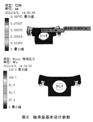
As shown in Figure 5, when the wall thickness of the bearing seat is A = 35mm, the maximum deformation of the T-groove is 0.09797mm, and the maximum stress of the bearing seat is 135.9MPa.
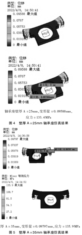
When the wall thickness value of the bearing seat A increases from 15mm to 35mm, the maximum deformation is from 0.09378mm to 0.09588mm to 0.09797mm, and the maximum stress is from 134.8MPa to 133.4MPa to 135.9MPa. The deformation is increased by 0.004mm, and the stress value is reduced by 1.1MPa. In the whole simulation process, the deformation of the bearing seat and the reduction of the stress value do not change much, so when the work roll bearing seat is reasonably designed, the value of wall thickness A should not be too large under the condition of ensuring the strength of the bearing seat. In the case of conditions, we should try to choose bearings with large outer diameter and strong carrying capacity.
The analysis of the following design drawings shows that the bearing seat section "A" in the vertical plane (as shown in Figure 6) is not the only important factor under the complex and large load cycle of roll bending force. The transverse bearing seat section "B", especially the section "C" where the load is applied, is also very important.
In Figure 6, a = 0.0625×D, b = 0.1×D. Although the design wall thickness A of the bearing seat does not have much influence on the stress and strain of the bearing seat itself, in the actual design process, the value of wall thickness A corresponds to the size of the hole D of the bearing seat. By referring to the picture and formula in the paper and entering the bearing outer diameter, the minimum wall thickness A required in the design process can be calculated, and the value is greater than the calculated value.
4 Conclusion
(1) Using finite element software, a static finite element model was established to calculate the stress distribution and deformation at the interface end of the T-shaped connecting rod of the bending roll hydraulic cylinder and the thin wall thickness of the bearing seat under the action of the bending roll force, and the influence of different design variables on the deformation of the bearing seat could be analyzed.
(2) It provides a theoretical basis for the design of work roll bearing seat of rolling mill. It can be seen from the simulation results that with the increase of the thickness of the wall thickness A of the bearing seat, the stress concentration at the bearing seat basically does not change, while the deformation at the end only increases by 0.004mm, which can be ignored.
The bore bore diameter should be increased as much as possible under the consideration of the design permit and the overall coordination of the part design. Regarding the wall thickness of the bearing seat, considering the relationship between the bearing seat and the strength, it is generally appropriate to consider the thickness of the wall thickness A to be 20mm ~ 30mm.
【 Reference 】
[1] Cheng Daxian. Mechanical Design Manual [M]. Beijing: Chemical Industry Press, 2016.
[2] Zhou Zhiping, Yang Xuchao. Finite Element Analysis and Design Application of roll Bearing Seat in Plate Mill [J]. Metallurgical Information Guide, 2018 (5) : 54-58. [3] Zou Jiaxiang. Steel rolling machinery [M]. Beijing: Metallurgical Industry Press, 2005.