Abstract: In view of the serious failure and short life of 241 series self-aligning roller bearings used for rolling mill reducer in a steel mill, the failure causes of the bearings were analyzed, and it was concluded that the bearings were subjected to greater axial force and impact force. Based on the original bearing structure, the design improvement is made, and the processing method of large steel cage is described. It has been verified by practice that the optimized bearing has good effect after application, and its life is greatly improved.
Key words: reducer; Aligning roller bearing; Cage; Design improvement; Pocket machining
0 Preface
Rolling bearings are industrial base parts, known as mechanical joints [1]. Self-aligning roller bearings can bear axial and radial bidirectional loads, and have the function of self-aligning, which can compensate for shaft bending deformation and misalignment of mating surfaces, so they are widely used in industrial gearboxes, known as "universal bearings" [2-5]. However, the real working conditions are very complex, and there is no perfect shaft bearing to adapt to all occasions. The stress and roller movement of aligning roller bearings in industrial gearboxes are described in detail in literature [3]. Under the condition that the ratio of axial force to radial force is too large and the impact load is too large, the rolling body will be loaded in a single column, which will generate additional impact load, and the rolling body and cage will be easily damaged, resulting in premature bearing failure, which will not reach its calculated life and affect the use of the reducer. However, no solution is given. Therefore, combined with examples, the author of this paper has optimized the design of the aligning roller bearing used in the mill reducer, and discussed the solution.
The main reducer of hot rolling production line of a steel mill in China is driven by helical gear, and the bearings are 241 series aligning roller bearings. The inner diameter of the bearings reaches 480mm, the outer diameter is 790mm, and the width is 308mm, which belongs to large bearings. During the use of the reducer, the bearing life is short and easy to be damaged. After analyzing the damaged bearing, the bearing structure is improved and processed without adhering to the conventional design ideas. After application, the life of the bearing is greatly improved, and the production halt and bearing replacement cost are reduced.
1 Original bearing structure and operating conditions
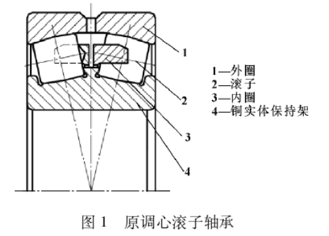
The fixed end bearing of the high-speed shaft of the reducer uses 241 series CA type aligning roller bearings, and the bearing structure is shown in Figure 1. The bearing is composed of an outer ring, an inner ring, a rolling body, a turning cage and a fixed middle rib. The outer ring has an oil injection hole, and the inner ring has an outer guard edge. Ring material GCr15SiMn. Precision P0 level, clearance C0 level. Bearing speed 0 ~ 180 ~ 425 r/min. Operating temperature -25 ~ 50℃. 460# gear oil cycle lubrication. As the bearing force situation is unknown, during which respectively tried:
(1) The number of bearings, copper cage structure and rollers of a foreign company have tried 22 and 21 grains respectively, and the bearing life of the company is 5 to 6 months. The failure form is broken tooth of copper cage.
(2) A domestic company's split steel cage, the life of about 4 months, the failure form is the steel solid cage bottom pair fracture.
(3) The CA structure of the bearings of a foreign company and the four and a half cages riveted, the rivets are misaligned.

It can be seen that the cause of bearing failure is cage damage. In addition, after observation, the inner ring of the failed bearing has an abnormal track trace on one side.
2 Failure cause analysis
After analysis, it is believed that the causes of premature bearing failure are as follows:
(1) Because the reducer is driven by helical gear, the bearing is installed at the fixed end of the drive shaft, and the bearing bears a large axial force. The 241 series self-aligning roller bearings are designed to bear large radial forces and weak axial load bearing capacity.
(2) There is a case of single column loading. This kind of bearing clearance is greater than 0 and the ratio of axial force and radial force is large to a certain extent, the following situations occur:
Fa/Fr > tanα
Where :Fa is the axial force; Fr is radial force; Alpha is the contact Angle. In theory, there will be a single column load. When the roller is loaded in a single row, the unloaded roller will slip, resulting in the risk of damage in the running of the bearing [4]. The single column load makes the roller speed difference on both sides, the cage running speed is different, the load column speed is higher, and the cage performance has higher requirements.
(3) In the process of use, the vibration is large, there is a large impact load, so that the cage to withstand the greater impact, brass and the same size of carbon steel cage is not enough to bear the vibration and impact.
(4) The fixed middle rib of the bearing cannot be moved axially, and the load of the two rows of rollers cannot be adjusted, which aggravates the uneven force of the two rows of rollers.
3 Design optimization scheme
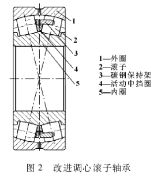
According to the above working conditions, the bearing is optimized, and the specific structure is shown in Figure 2. The optimization idea is to increase the thickness of the cage and enhance its carrying capacity without changing the bearing dimension (installation position limit) and bearing capacity. The specific design optimization scheme is as follows:
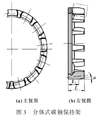
(1) The split carbon steel cage is used to replace the brass cage, the material is selected 20 steel, and the relevant size of the cage is increased to strengthen its strength and bearing capacity.
(2) Increase the tooth width of the cage. There are two options: the first option is to keep the number of rollers constant and reduce the diameter of rollers; The second solution is to keep the roller diameter unchanged and reduce the number of rollers. Due to the complex bearing capacity of the shaft in the working condition, in order to ensure that the roller has sufficient bearing capacity, it is not advisable to reduce its diameter, so choose the second scheme and determine that the number of rollers is reduced to 20.

(3) The length of the roller is reduced from the original 128mm to 120mm to increase the cage beam width. Due to the shortening of the roller, it is necessary to pay attention to the size L1 of the cage outer diameter opening lock in Figure 3. If improperly selected, the roller will easily fall out of the cage during assembly. In this example, L is 105 mm, α is 13°, and L1 is 90mm, which is appropriate after installation.

(4) Cancel the fixed middle baffle and use the active middle baffle ring. The main difference between the movable retaining ring and the fixed retaining edge is that when the bearing is running, the fixed retaining edge cannot be moved axially, but it guides the roller well. When the axial load is borne, the load of two rows of rollers cannot be adjusted, which easily leads to the stress of a single row of rollers or stress concentration. In the activity, the stop ring can be moved axially to compensate for the left and right, and when the bearing is under axial load, the load of the two rows of rollers can be adjusted to make it evenly loaded and avoid stress concentration. If there is no moving center retainer, its function is assumed by the cage [7].
(5) Bearing dimensions and ring wall thickness remain unchanged to ensure installation. Other technical requirements meet the current national and industry standards, such as form and position tolerances, heat treatment, flaw detection and detection methods.
4 big hole cage processing
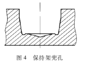
The difficulty in the realization of the above design scheme is the processing of the hole of the large carbon steel cage [8-9]. The shape of cage pocket hole is shown in Figure 4, and its structure is modeled after the rolling body. TK9213 horizontal drilling machine is used for traditional copper cage hole processing, and the cutting tool uses high-speed steel copying bit. After increasing the cage hole aperture, the drill diameter should be increased accordingly. After the cage material is changed to steel, the cutting force is large and the drill bit is easy to burn. The plastic deformation zone produced by the traditional drilling process is larger than the thickness of the cutting layer, which is easy to produce a large number of burrs after processing, affecting the use of drilling.

Based on the above reasons, the processing of the large pocket hole of the steel cage is changed to the milling mode. Because the milling surface includes the side wall and the bottom of the pocket hole, the 90° rotary vertical milling cutter is selected for milling. The blade material selection of Sentai inge EB1220, not only can meet the cutting performance requirements of high speed and large feed, but also can use the side edge machining of the tool in milling, cutting force is small, the tool can be reused, reduce the preparation time of the tool, reduce the cost. Compared with traditional drilling, the difference between the plastic deformation zone and the thickness of the cutting layer is smaller and the burrs are less. The specific implementation scheme is detailed in the literature [10], which adopts the automatic programming method. The machining method has been verified in the manufacture of a variety of large-bore bearing solid cages in a bearing factory. It is economical and reliable, the processing efficiency is high, and the accuracy of the cages meets the requirements.
5 Closing remarks
The improved bearing has been installed and used for more than one year, and there is no failure at present, which far exceeds the life of the original foreign bearing. It should be noted that the design optimization scheme is carried out when the bearing force is unknown. If the conditions allow, the bearing force should be accurately detected, and then the bearing selection or design improvement should be carried out. Bearings belong to the basic precision structure, can not be blindly selected.
【 Reference 】
[1] Xue Jinxue, Jia Songyang, Yang Baisong. Analysis of Superfinishing Conical Roller grinding based on removal rate of arc length material [J]. Coal Mine Machinery, 2015,36 (12): 124-126.
[2] Li Bing. Stress analysis of Main Drive Reducer bearing of Rolling mill [D]. Wuhan: Wuhan University of Science and Technology, 2010.
[3] Zhuo Fuhai. Application Characteristics Analysis of aligning roller Bearing in Industrial Gear Box [J]. Mechanical Transmission, 2016(10):162-165.
[4] CAI Shumei, Jiang Haicheng. Selection Analysis of bearing and Seal of Output end of Mineral Planetary Reducer [J]. Coal Mine Machinery, 2016,37 (5):70-71.
[5] Chen He, Liu Jianxiu. Improvement of bearing Selection Layout of Reducer for scraper conveyor [J]. Coal Mine Machinery, 2012,33 (1):181-183.
[6] Xiao Ying. Gear box bearing skid damage and preventive measures [J]. Mechanical Engineer, 2014(2):52-54.
[7] Luoyang LYC Bearing Co., LTD. Bearing product sample [Z]. 2011.
[8] Huang Jian, Liu Guangshi, Li Xiao, et al. Improvement of Process Method of aligning roller Bearing cage [J]. Journal of Bearing, 2013(11):25-27.
[9] Wei Guangguo. Measurement of pocket hole of Solid cage of Large aligning roller bearing [J]. Journal of Bearing, 2003(3):28-29.
[10] Chu Jianyang, Zhang Xin, Wang Pengwei, et al. Machining of Large Aperture Hole in Solid Steel cage of aligning roller bearing [J]. Journal of Bearing, 2017(3):19-21.