According to incomplete statistics, 16% of motor bearing failures are related to improper installation. In the general installation process of motor bearings, we emphasize a series of operating environments, operating processes, and operating methods, but in fact, there are still many front-line production personnel who adopt improper installation methods for bearings.
For bearings commonly used in motors - deep groove ball bearings, the most typical of these improper operations is the "knock" on the bearing. There are two general patterns of tapping:
· First, the percussive impact load does not pass through the bearing rolling body;
· Second, through the bearing rolling body.
The installation load, or the installation knock, within a certain limit as long as it does not pass through the rolling element of the bearing, then the damage to the bearing is controllable. Control the knocking force, will not cause serious damage to the bearing.
However, for the installation force through the percussion installation of the rolling body, it will cause damage to the bearing, in other words, it is an important potential cause of bearing damage. In serious cases, plastic deformation is left on the surface of the bearing raceway, and there is noise when the bearing is running. Fortunately, such problems are easy to spot. Then, there is a slight deformation in the raceway part of the other bearing, but the deformation does not lead to macro signs when the bearing is in operation. With the further continuous operation of the bearing, the bearing raceway begins to appear fatigue failure at the initial damage site, so that the bearing noise can be heard.
At this time, the motor has been running under this condition for a period of time, if the maintenance personnel notice the noise in time to replace the maintenance, the consequences are more controllable; However, if the maintenance personnel ignore the noise information of the bearing (especially in some conditions with very large environmental noise), the bearing is easy to eventually fail and burn or even cause greater losses.
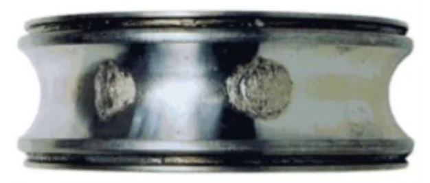
In this case, the failure of the bearing will appear as follows:

The failure form seems to belong to the subsurface fatigue (sub-surface fatigue), but its failure traces have inherent characteristics, the largest point is that the fatigue points are equally spaced, and the spacing is equal to the spacing between the bearing rolling elements.
With these characteristics, it can be more confident to judge the failure of the bearing raceway caused by the tapping during installation. Because, the fatigue point of equal rolling element spacing on the raceway surface indicates that there is initial fatigue damage at the place of equal roller spacing. If the fatigue occurs when the bearing is running, because the rolling body is moving in a circle on the raceway, there is no way to stop and present the damage of equal roller spacing.
Therefore, this damage can only be caused by the further development of the initial damage caused by the presence of a strong external force when the bearing is stationary.
After the motor is installed, the chance of bearing a huge radial load when it is not running is small, so it is likely to be knocked during installation. (Unlike the damage under vibration conditions, the distance between the failure points in this case is not necessarily equal to the roller distance, he explained separately.)
Another commonly used bearing in motors is a cylindrical roller bearing. The most common damage of cylindrical roller bearings in the installation process is the axial strain between the bearing raceway and the rolling element.
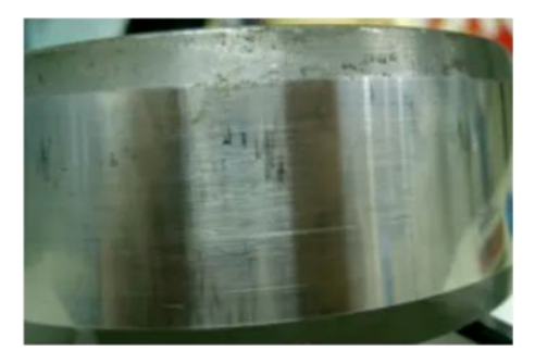
The following is a typical cylindrical roller bearing installation caused by raceway strain marks:

Shown in the picture is a NU cylindrical roller bearing inner ring. The surface of the inner ring has some traces along the axis, and the typical characteristics of these traces are: along the axial distribution of the bearing, the failure trace presents an axial stretch trace (if observed with a microscope, it will be found that the direction of the knife mark on the metal surface changes), and in many cases, it presents a triangle shape with a large and small head.
This failure trace is sometimes equal to the roller spacing, and sometimes shows a similar equal distribution. Especially after multiple installations, it is likely that the complete trace of equal roller spacing will not appear.
However, a failure trace and other roller spacing can often be found in other similar traces.
The formation of such marks is related to the installation process. Usually, when installing cylindrical roller bearings, the inner ring of the bearing is first hot sheathing to the shaft, the outer ring is installed on the bearing end cover, and then the end cover with the outer ring of the bearing is placed on the inner ring of the bearing and pushed in the direction of the inner ring of the bearing. This "pushing" process often causes strain in the bearing raceway, thus forming marks similar to those in the picture. Such traces will appear in the early stage of the motor bearing noise, later with the development of failure, there will be more complications.
Whether it is the installation damage of ball bearings or cylindrical roller bearings, if you look at the frequency domain vibration of bearings when the motor is running, you will find the defect frequency of the bearing ring, and the failure trace similar to the picture will be found when the bearing is disassembled. But depending on the degree of failure, the severity of the trace is different.
If the electrical engineer encounters the disassembled bearing with the above picture characteristics, he can find a thorough solution to the problem in the installation of the bearing.