
Abstract: The contact and deformation analysis model of the interaction between roll and bearing system in Senkimir mill was established and solved by finite element method. The contact load, contact stress and deformation distribution of the bearing system of Senkimir mill with single and two-roll support under given rolling conditions are studied. The contact behavior of bearing system under different rolling conditions with single roll support is analyzed. The results show that under the same rolling conditions, the inner contact stress and outer ring contact deformation of the bearing under single roll support are greater than that under double roll support. With the increase of rolling force, the inner stress of bearing and the contact deformation of outer ring increase obviously when a single roll is supported.
Key words: Senkimir mill; Rolling mill bearing; Roller bearing; Contact load; Contact stress; Contact deformation; Finite element
1 Introduction
With the increase of high precision sheet steel market demand, the 20-high Senkimir mill has been rapidly developed and widely applied, but its key technology research needs to be solved [1-4]. The 20-high Senzimir mill has a solid frame of monolithic casting, and the supporting roll device composed of bearings and mandels is in the form of multi-fulcrum beams. Rolling force is distributed radially to each supporting roll device through the middle roll, and then transmitted to the overall frame along the length of the roll body [2]. The support roller bearing is rotated by the outer ring, the linear speed can reach 800 ~ 1000m/min, the unit pressure under it is 2 ~ 4 times higher than that of ordinary bearings, and the pv value is 3 ~ 20 times that of general purpose bearings. However, due to the limitation of technical level, the current products are often prone to fatigue, fracture, burning and other failure phenomena.
Senkimir mill bearing is a high-tech product in metallurgical bearing. The research on the core technology of this product involves the identification and integration of many key technologies. Senkimir rolling mill bearing technology is the most mature in SKF and Schaeffler in Europe, while KOYO, NSK and Timken in Japan have also reached a high level, but the relevant technical literature with this bearing containing many advanced technologies is extremely limited. Reference [5] numerically simulates the vibration characteristics of the roll system of Senkimir mill, according to which the failed mill bearings are identified. In previous studies, the support roll device was simplified into a solid roll, and a simple finite element model and contact element method were used to analyze the effects of parameters such as rolling force and strip width on roll deflection and roll gap pressure distribution [6]. However, this simplification does not apply to the study of bearings and support roll bearing systems for Sunkimir rolling mills. The research on the contact force and deformation of the bearing unit in the Senkimir mill and between the roll and the bearing unit is also very rare [7-9]. In the design structure, the roller backing bearing and the mandrel together constitute the support roll system. The study involves not only the interaction between the bearing unit and the intermediate roll, but also the interaction between the bearing assembly. In addition, because the four support rolls at the top of the rolling mill and their corresponding intermediate rolls have single and double roll support forms, the internal mechanism of the bearing unit is also different. On the other hand, considering that each back-up roll has 5 to 8 sets of bearings to form the backing roller bearing system, the research is more complicated. Therefore, the research on the key technology of systematical identification and technology integration of Sunkimir mill bearing group can be carried out by decomposing complex model method. For example, firstly, the contact behavior of bearing unit and single and double roll support is studied. Then, under the given external conditions, the contact mechanism inside the bearing unit is studied. In addition, technical research on raceway design or roller macro and micro topological design around bearing microscale design can also be carried out, including so-called crown and clearance analysis; The contact mechanism of H-value control of bearing outer ring wall thickness difference is also included in the research of group key technology involved. Therefore, Sunkimir rolling mill bearing product development is a systematic research work, with a group of key technologies to identify and integrate high-end bearing characteristics.
As an important work in the identification and integration of key technology of Sunkimir rolling mill bearing group, the coupling system composed of roll and bearing unit of typical 20-high Sunkimir rolling mill with high speed, heavy load and precision characteristics is taken as the research object, and the mechanical model of the interaction mechanism of bearing unit and roll system is established. Through comparative study, the contact behavior between the bearing unit and the intermediate roll under different rolling force conditions is analyzed. At the same time, the contact behavior of roller inside bearing unit is studied and analyzed to support the contact stress and deformation distribution law between bearing unit and roll. Through the above research, the numerical test mechanism analysis basis is provided for the identification of the microscale design technology, process control technology and installation service technology of Sunkimir rolling mill bearing products.
2. Model and method
2.1 Roll bearing system model
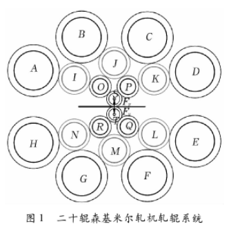
The working principle of the 20-high Senkimir mill is shown in Figure 1. The rolling force Fz of the 20-high Senkimir mill is transferred from the work rolls S, T through the intermediate rolls I, J, K, L, M, N, O, P, Q, R to the support roll device A, B, C, D, E, F, G, H; It is finally passed on to a solid integral frame to ensure a small thickness deviation in the width direction of the steel strip [7]. The backing bearing of the Sunkimir mill works at high speed and heavy load, and its outer ring is in contact with the middle roll as the supporting roll face. Each support roller usually consists of 5 to 8 sets of two or three columns of cylindrical roller bearings as backing bearings installed on the same single shaft, through the outer ring and the middle roller non-conformal contact conduction rolling force, the outer ring is easy to deformation, change the bearing internal load distribution, affect the bearing capacity. The 4 second intermediate rolls I, K, L, N on both sides of the center line of the rolling mill are transmission rolls, which are driven by the motor through the universal joint shaft; The two work rolls are driven by the friction between the four drive rolls and the first intermediate rolls O, P, Q, R. The test and installation show that the bearing outer ring usually occurs different forms of fracture phenomenon, so the research on the contact mechanism between the outer ring and the intermediate roll on the premise of considering the internal structure design of the bearing unit is of great practical significance for the identification and development of bearing product microscale design technology.
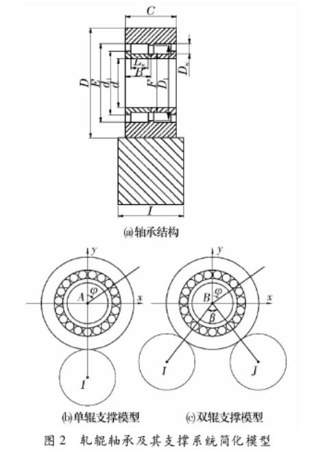
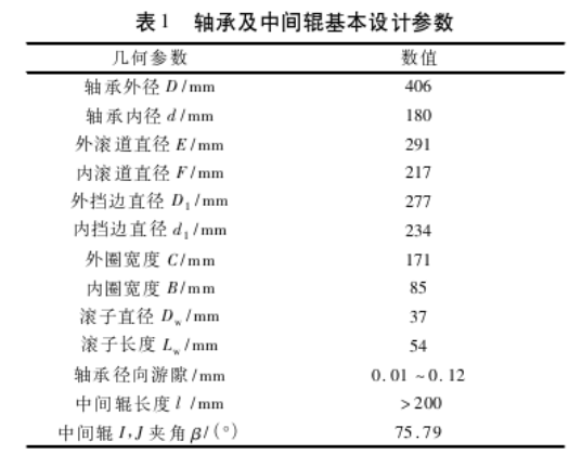
Typical Senkimir rolling mill bearings are studied. Their structural forms and basic design parameters are shown in FIG. 2a and Table 1 respectively. Considering the different support forms of bearing units, a mechanical model was established to study the interface contact mechanism between the backing bearing units and the intermediate rolls of two typical Sunkimir rolling mills, as shown in FIG. 2b and FIG. 2c. It is worth mentioning that according to the iterative property of the numerical test of contact mechanics, the established contact mechanics model has taken into account the problems of stress concentration and iterative sensitivity of the numerical test between all contact interfaces, so as to improve the efficiency and accuracy of the numerical test.
2.2 Working Conditions
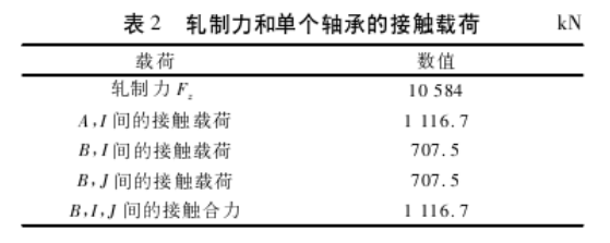
With the different position of the work roll, the direction Angle of the applied force of each roll constantly changes, and the force is also different [2]. The design maximum rolling force Fz of this type of Senkimir mill is about 10584kN, the friction torque of the roll system is ignored, and the rolling force is set on the concentric line of the upper and lower work rolls, as shown in Figure 1. The roll system is arranged symmetrically, each roll is the standard diameter, and the contact load of the support roll is 6700kN, and there are 6 sets of backing bearings on each support roll, and the contact load between the rolling force and a single bearing is obtained, as shown in Table 2.
2.3 Contact mechanics model
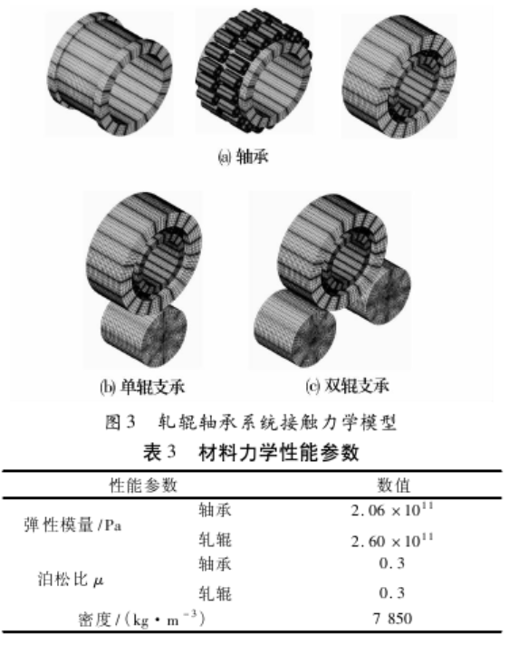
The finite element contact mechanics model of the coupling system composed of the roll and bearing unit of the Senkimir mill was established for the analysis of the contact performance between the single and two-roll support bearing and the roll [10](FIG. 3). The material mechanical property parameters are shown in Table 3. In the modeling process, the roll length is slightly larger than the bearing width, and the rest is ignored. Without affecting the calculation results, the bearing structure is appropriately simplified, without considering the influence of the lubricating oil hole in the bearing inner ring and the sealing groove in the outer ring, the roller circumferential and axial constraints are used to simulate the cage action, and the mesh is refined in the contact area and the area with possible stress concentration to ensure the calculation accuracy and the efficiency of numerical iterative solution. The contact mode between interfaces can be established by using the surface interpolation technology. There are 77 contact pairs in the single-roll support model of roll bearing system AI and 78 contact pairs in the two-roll support model of BIJ. The contact pair is mainly set to facilitate the control of the relative position of the interface nodes that may be contacted in the numerical iteration of contact mechanics. In addition, the contact numerical algorithm adopts the augmented Lagrange method.
3 Calculation Results
By finite element numerical calculation, the contact properties of bearings and rollers supported by single roll and double roll are compared under the same working conditions, and the stress and deformation distribution of bearings supported by single roll with different rolling forces are further obtained. Set 2 load substeps, automatic time step; The running time is about 30min, and the single and two-roll support models are stably convergent after 7 and 5 steps of balanced iteration, respectively, and the data is read and processed. The mesh is double encrypted, and the relative error of the two times is less than 5%, which eliminates the numerical sensitivity caused by the mesh density and stress concentration in the numerical iteration process.
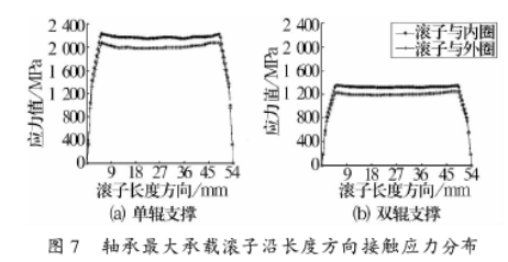
Under the maximum rolling force and given a clearance of 0.1mm, the distribution of stress and deformation of bearings supported by single and double rollers is compared as shown in FIG. 4 to FIG. 6. FIG. 4a and FIG. 4b show the distribution of the contact stress between the intermediate roll and the outer diameter surface of the bearing unit along the bearing width direction and the circumference direction in the form of single roll support and double roll support, respectively. FIG. 5a and FIG. 5b respectively compare the circumferential deformation in the middle of the bearing outer diameter with the comprehensive Mises equivalent stress distribution under single and double roll support. FIG. 6a and FIG. 6c show the Mises equivalent stress distribution in the middle of the inner and outer raceway surface of the bearing under single roll support, respectively. FIG. 6b and FIG. 6d show the Mises equivalent stress distribution on the middle surface of the inner and outer raceway of the bearing under two-roll support, respectively. When single and double rollers are supported, the contact stress distribution of the roller with the largest load along its axis is shown in Figure 7.
Given the clearance of 0.1mm, the stress and deformation distribution of single-roll supported bearings were shown in FIG. 8 and FIG. 9 when the rolling force was selected to be 5000,10000 and 15000kN respectively (that is, the contact load of bearings was 527.5,1055.1 and 1582.6kN). FIG. 8a and FIG. 8b show the distribution of the contact stress between the intermediate roll and the bearing outer ring along the bearing width direction and the circumference direction under different rolling forces, respectively. FIG. 9a and FIG. 9b respectively compare the circumferential deformation and Mises equivalent stress distribution of bearing outer diameter under different rolling forces.
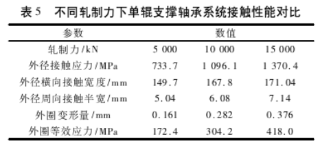
The finite element solution and Hertz theory solution of bearing contact stress distribution under single maximum rolling force and two-roll support are shown in Table 4. The comparison results of the distribution of stress and deformation of bearings supported by single roll with different rolling forces are shown in Table 5, in which the maximum values of the opposite ratios are shown in the figure. It is worth mentioning that the Hertz stress can only approximate the contact stress between simple characteristic contact interfaces, and the accurate analysis considering the overall structure of the bearing unit of the Sunkimer mill and the contact behavior between the outer ring and the intermediate roll interface has great limitations [11]. Therefore, the Hertz theoretical calculation results are only for reference.
4 Discussion
4.1 Bearing system contact performance analysis
It can be seen from Table 2 that the contact load of the backing bearing supported by a single roll at the maximum rolling force is the same as the contact load force supported by a double roll, which is about 1116.7kN. Under the same contact load condition, the stress and deformation distribution of the single roll support model and the two-roll support model with a given clearance of 0.1mm are compared.
It can be seen from FIG. 4 that the contact stress distribution curves between the outer ring and the middle roller are similar when single and double rolls are supported. Because the contact load of the bearing supported by two rollers is smaller than that supported by a single roller, the contact stress amplitude and contact width of the bearing outer ring supported by two rollers are smaller than that supported by a single roller. As can be seen from FIG. 6, the internal equivalent stress of the bearing supported by a single roll is significantly higher than that of the bearing supported by a double roll. In the case of the two-roll support, 9 rollers are stressed at the same time and are relatively balanced, while in the case of the single roll support, only 7 rollers are stressed, and the magnitude difference is obvious, which aggravates the stress concentration in the form of the single roll support. The comparison between FIG. 4 and FIG. 6 and Table 4 shows that the stress and deformation distribution of bearings supported by a single roll is more concentrated and the value is larger than that of bearings supported by a double roll. Obviously, under the same working condition load and clearance parameters, the bearing supported by a single roll is more likely to fail.
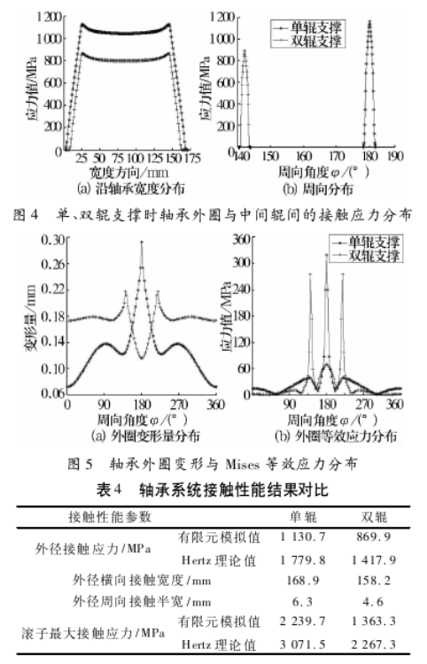
As can be seen from FIG. 5a, when a single roll is supported, the bearing outer ring deforms greatly at φ=180°, while the deformation on both sides is relatively small, and the drop between crest and trough is 0.171mm. The deformation is also relatively concentrated near φ=90° and φ=270°, and the drop is 0.065mm, which can produce large bending stress. Prone to fracture and other failure phenomena; The deformation of the outer ring supported by two rollers is relatively balanced, but there is a certain mutation at φ=142°,180°,218°, the maximum drop is 0.102mm, and there is also a risk of fracture. It can be seen that the non-conformal contact between the bearing and the roll will cause large deformation and sudden change of the bearing, which will change the internal load distribution and bring adverse effects.
It can be seen from FIG. 5b that the Mises equivalent stress increased obviously in the outer diameter of the bearing and roll contact area, which was caused by the simultaneous contact superposition of the outer ring with the roller and the roll, and the stress peak value in other areas was mainly affected by the roller contact load. As in FIG. 5b and FIG. 6, the maximum stress value is also formed by the simultaneous contact superposition between the outer ring and the roll and the roller, and other extreme value points are mainly generated by the contact between the roller and the outer ring. It can be seen that during the rolling mill operation, the contact performance parameters such as the peak stress of the bearing outer ring change constantly with the different relative positions of the roller and the roll, and the analysis in this paper is only the most unfavorable complete superposition condition.
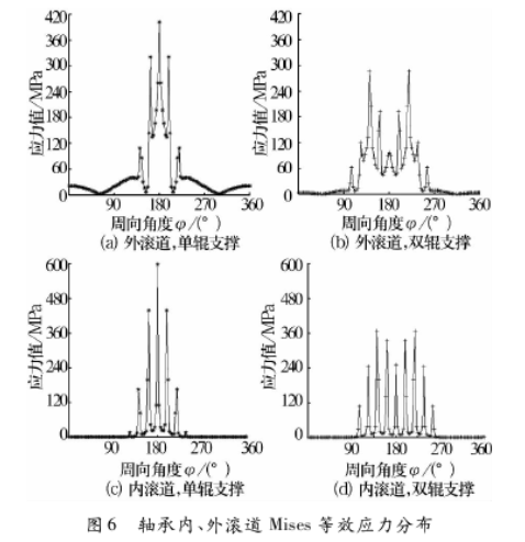
As can be seen from Figure 7, the contact stress of the maximum bearing roller is 2239.7MPa, the maximum contact deformation is 0.05mm, and the position is φ=180° when a single roll is supported. The contact stress of the maximum bearing roller is 1363.3MPa and the maximum contact deformation is 0.048mm, which is located at φ142 ° and 218°.
4.2 Further analysis of contact behavior of single-roll support bearing system
According to the analysis results of the single roll support model and the double roll support model, the contact state of the bearing is more dangerous when the single roll support is used. Therefore, under the given clearance of 0.1mm, the rolling force is selected as 5000,10000 and 15000kN respectively, and the stress and deformation of the bearing when the single roll is supported are further analyzed and studied.
It can be seen from Figure 8a that when the rolling force reaches 5000kN, the contact stress distribution is obviously shorter than the bearing width. When the rolling force is 10000kN, the maximum contact stress is 1166.7MPa, and the contact stress at the edge is close to zero. At this time, the size and regional distribution of the contact stress between the roll and the bearing are still reasonable. When the rolling force increases to 15000kN, the maximum contact stress reaches 1370.4MPa, the contact stress is distributed in the entire bearing width direction, and the stress at the edge is higher than 160MPa, which will lead to increased bearing load in the sealing area on both sides of the bearing, and the bearing is prone to premature failure. It can be seen that the structural parameters of the bearing of Senkimir mill are suitable for the working load of the maximum rolling force of 10584kN.
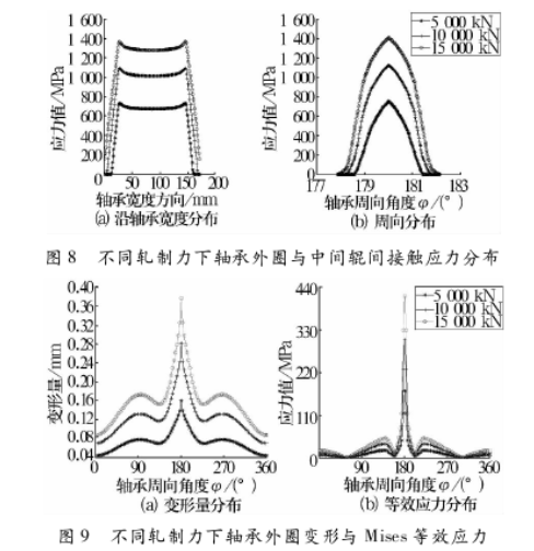
According to FIG. 8 and FIG. 9, it can be seen that the changes of roll and bearing contact width, contact stress, outer ring deformation and Mises equivalent stress. With the increase of rolling force, the deformation and stress concentration of the outer ring become more and more prominent: the maximum drop between the deformation crest and trough increases from 0.090mm at 5000kN to 0.164mm at 10000kN, and then increases to 0.223mm at 15000kN. The maximum drop between the stress crest and trough increased from 167.5MPa to 295.0MPa and then to 404.5MPa. It can be seen from Table 5 that the contact width, contact stress, deformation and Mises effect force between roll and bearing increase nonlinearly with the increase of rolling force. When the rolling force is increased by 2 times, the maximum contact stress between the outer ring and the roll increases by 86.8%, while the transverse and circumferential contact widths increase by 14.3% and 41.7% respectively. At the same time, the outer ring deformation and the outer ring Mises equivalent stress were increased by 1.34 and 1.42 times, respectively. Considering the stress and deformation comprehensively, it can be seen that overloading conditions are easy to cause fatigue wear, fracture and other failure phenomena of bearings. In fact, the test of the backing bearing of the Sunkimir mill and the installation practice of the steel plant show that the fracture of the bearing outer ring and the adhesive wear caused by the lubrication failure between the outer ring and the intermediate roll interface are closely related to the working load, the interface processing quality and the emulsified lubrication fluid. The results in this paper can be used to explain the similar problems mechanically.
(1) The developed multi-interface contact mechanical model of support roll bearings of Sunkimir mill can obtain numerical simulation of the contact behavior mechanism of single-roll and two-roll support bearing systems under given rolling conditions.
(2) Under the same load conditions, the contact width between the outer ring and the intermediate roller and the Mises equivalent stress of the raceway in the single-roll supported bearing system were larger than those in the two-roll supported bearing system.
(3) With the increase of rolling force, the contact performance of the single-roll support bearing system changes significantly.
The research results are conducive to further research on the contact behavior mechanism and failure mechanism of the coupling system between the bearing unit and the roll of typical high-speed, heavy-duty and precision Senkimir rolling mill, and provide a theoretical basis for the development of micro-scale design technology.
【 Reference 】
[1] McCann J. verview of WorkRolls for ColdRolling [J]. Ironmaking&Steelmaking, 2000,27 (1):15-18.
[2] Tsai Chonglun. Structure Analysis of 20-high Senkimir Mill [J]. Metallurgical Equipment, 1980(3):9-21.
[3] Chinese Society of Mechanical Engineering. China Mechanical Engineering Technology roadmap - Bearing [M]. Beijing: Science and Technology Press, 2011:207-219. (in Chinese)
[4] Key technologies of bearing industry upgrading and development technology and product group [R]. i BIT(UMG), 2011:1-56.
[5] Brusa E,Lemma L.Vibration Analysis of a SendzimirColdRolling Mill and Bearing Fault Detection[J]. Journal of Mechanical Engineering Science,2010,224 (3):1 645-1 654.
[6] Yu Hai-liang,Liu Xiang-hua.Analysis ofRoll Gap Pressure in Sendzimir Mill by FEM[J].Journal of Iron and SteelResearh International,2008,15(1):30- 33.
[7] Arif Sultan Malik.Rolling Mill Optimization Using an Accurate andRapid New Model for Mill Deflection and Strip Thickness Profile[D].Wright State University, 2007.
[8] Ringwood J V.Shape Control Systems for Sendzimir Steel Mills[J].IEEE Transactions on Control Systems Technology,2000,8(1):70-86.
[9] Mukhopadhyay G,Bhattacharya S.Failure Analysis of a CylindricalRoller Bearing from aRolling Mill[J].J. Fail.Anal.and Preven.,2011(11):337-343.
[10] Xi H,Wang Z Q,Guo H Y,et al.Contact Mechanism of FourRow CylindricalRoller Bearing on MillRoller [C].World Tribology Congress,2013.
[11]Wang Feng-cai,Wang Han-yu.Contact Mechanics of Spherical/Aspheric Bearings[M]//Encyclopaedia of Tribology.Berlin:Springer,2013:470-477.