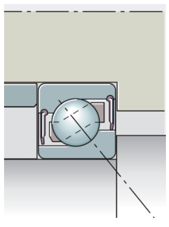
Angular contact ball bearings are a commonly used type of bearing, which require excellent rotational speed performance and load-carrying capacity. Compared with deep groove ball bearings, in addition to having a good radial load-carrying capacity, it also has an excellent axial load-carrying capacity. Meanwhile, due to the unique structure and load-carrying characteristics of angular contact ball bearings, they can only withstand unidirectional axial loads (for a single bearing), which also puts forward some requirements for the use of this type of bearing. First, we observe the internal structure of the angular contact ball bearing, as shown in the following figure:

As can be seen from the figure, the internal structure of the angular contact ball bearing determines that this bearing can only withstand axial loads in one direction, and the direction of this load is between the thick edge of the inner ring and the thick edge of the outer ring of the bearing. If the bearing is subjected to the opposite axial load, it will show a tendency to disengage or may disengage, which will lead to the phenomenon that the rolling elements of the bearing cannot form pure rolling, and then cause the bearing to heat up and wear, and the bearing will fail prematurely.
Therefore, when angular contact ball bearings are put into use, it is necessary to avoid axial loads that are opposite to their axial load-carrying capacity. How can it be achieved? This is what we call axial preload.
As mentioned earlier, when a single angular contact is in operation, it is necessary to avoid the occurrence of an axial load inside the bearing that is opposite to its axial load-carrying capacity direction. Therefore, a preload needs to be applied in the direction of its axial load-carrying capacity. In the above figure, it should be the direction from the thick side of the outer ring to the thick side of the inner ring of the bearing.
So, how large should this load be? From the reasons for the axial preload of single-row angular contact ball bearings introduced above, it can be seen that this preload is to prevent reverse axial loads from the outside. That is to say, when there is a reverse axial load on the bearing from the outside, the preload of the bearing should be able to offset this load. From this, a conclusion can be drawn that the axial preload should be greater than the possible reverse axial load from the outside.
In addition, when the reverse axial load from the outside occurs, the load inside the bearing should meet its minimum load requirements. That is, on the basis of the maximum reverse axial load, add a minimum load of the bearing.
Of course, if there are other factors on the spot, they also need to be taken into consideration. As mentioned earlier, when a single angular contact is in operation, it is necessary to avoid the occurrence of an axial load inside the bearing that is opposite to its axial load-carrying capacity direction. Therefore, a preload needs to be applied in the direction of its axial load-carrying capacity. In the above figure, it should be the direction from the thick side of the outer ring to the thick side of the inner ring of the bearing.
So, how large should this load be? From the reasons for the axial preload of single-row angular contact ball bearings introduced above, it can be seen that this preload is to prevent reverse axial loads from the outside. That is to say, when there is a reverse axial load on the bearing from the outside, the preload of the bearing should be able to offset this load. From this, a conclusion can be drawn that the axial preload should be greater than the possible reverse axial load from the outside.
In addition, when the reverse axial load from the outside occurs, the load inside the bearing should meet its minimum load requirements. That is, on the basis of the maximum reverse axial load, add a minimum load of the bearing.
Of course, if there are other factors on the spot, they also need to be taken into consideration.
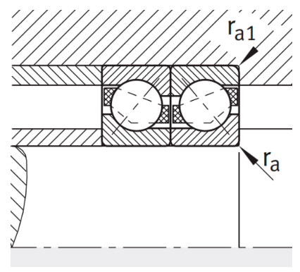
Since a single angular contact ball bearing can only withstand unidirectional axial loads, in conditions with bidirectional loads, paired angular contact ball bearings are used for face-to-face or back-to-back installation. Both installation methods involve the use of two single-row angular contact ball bearings, which are installed together in a way that the axial load-bearing directions are opposite. If the thick edges of the outer rings are installed together, it is a back-to-back installation; if the thin edges of the outer rings are installed together, it is a face-to-face installation. Whether installed face-to-face or back-to-back, the two angular contact ball bearings each bear the axial load in one direction. As shown in the following figure:

The picture shows a pair of diagonal contact bearings installed back-to-back. Among them, the bearing on the left bears the axial load from left to right on the shaft, and the bearing on the right bears the axial load from right to left on the shaft. From this schematic diagram, it can be seen that for angular contact ball bearings used in pairs, the axial load in any direction will be borne by one of the bearings. Therefore, preloading is generally not carried out by applying an external axial preload. However, this does not mean that angular contact ball bearings installed face to face or back to back cannot be preloaded. So, for this configuration of bearings, how is the axial preload applied to the two bearings?
Please look at the following picture:

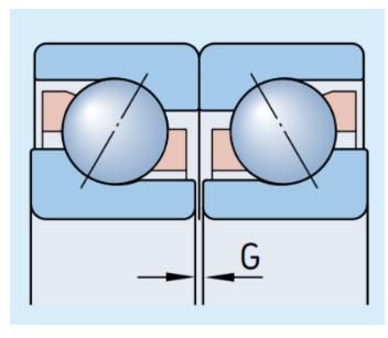
This picture shows a pair of angular contact ball bearings installed back-to-back. It is not difficult to find from the figure that when the internal clearance of the angular contact ball bearing is 0, its end faces are not necessarily on the same plane. The example in the picture shows the situation where the thick side of an angular contact ball bearing is higher than the thin side. When the thick sides of such two bearings are pressed tightly, there is a gap between the thin sides. If the thin sides are also pressed tightly with external force, negative clearance will appear inside the bearings, that is, there will be preload.
If the dimensions of the thin and thick sides are controlled in the production of bearings, the preload inside the two paired bearings can also be controlled. In fact, this is indeed the operation carried out in the production and use of bearings. This is why when two single-row angular contact ball bearings are paired, they need to be matched. This assembly work essentially involves controlling the end face dimensions to regulate the internal preload (clearance) of the bearing after installation.
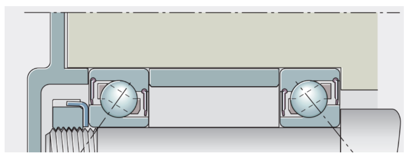
Except for angular contact ball bearings with two bearings installed face to face or back to back, sometimes a structure is used where two angular contact ball bearings are cross-positioned on both sides of the shaft. As shown in the following figure:

In the figure, the two angular contact ball bearings have no two ends of the shaft, and the bearings are separated by spacers. At this point, the internal clearance of the angular contact ball bearing is controlled by the size of the spacer ring. In the figure, for the angular contact ball bearings installed back-to-back, if the length of the spacer ring is large, the internal preload of the bearing will be large; otherwise, it will be small.
In the preload control of the aforementioned angular contact ball bearing, the user can also influence the internal clearance of the bearing by controlling the fit between the inner ring of the bearing and the shaft. The calculation of the reduction in clearance will be written in a separate article.
In conclusion, the internal clearance of the installed angular contact ball bearing operating under stable conditions is the combined result of factors such as the external control end face size, the fit size between the inner ring of the bearing and the shaft, and the reduction in clearance affected by temperature. The magnitude of the final preload should ensure that when the bearing is subjected to any axial load, the angular contact ball bearing at the non-load end should not be disengaged (the load is greater than the minimum load).
For the application of industrial motors, generally, paired angular contact ball bearings are directly installed together, eliminating the need for calculations and adjustments such as pairing. However, for some gearbox applications, this calculation must be carried out.